ITRF2014
Description
ITRF2014 is the new realization of the International Terrestrial Reference System. Following the procedure already used for the ITRF2005 and ITRF2008 formation, the ITRF2014 uses as input data time series of station positions and EOPs provided by the Technique Centers of the four space geodetic techniques (VLBI, SLR, GNSS and DORIS). Based on completely reprocessed solutions of the four techniques, the ITRF2014 is expected to be an improved solution compared to ITF2008.
Two innovations were introduced in the ITRF2014 processing, namely:
- Annual and semi-annual terms were estimated for stations with sufficient time-spans of the 4 techniques during the stacking processes of the corresponding time series;
- PSD models were determined by fitting GNSS/GPS data at major GNSS/GPS Earthquake sites. The PSD models were then applied to the 3 other techniques at EQ Co-location sites.
While the ITRF2014 solution provides the usual/classical estimates: station positions at a given epoch (2010.0), station velocities and EOPs, the PSD models are part of the ITRF2014 products.
Input data
Space geodesy solutions. The used time series of solutions of space geodesy are summarized in the following table, indicating for each one, the time span and the type of constraints.
Computation strategy
The strategy adopted for the ITRF2014 generation consists in the following steps:
- Apply minimum constraints equally to all loosely constrained solutions: this is the case of SLR weekly solutions;
- Apply No-Net-Translation and No-Net-Rotation conditions to IVS solutions provided in the form of Normal Equation;
- Use as they are minimally constrained solutions: this is the case of IGS and IDS weekly solutions;
- Form per-technique long-term solutions (TRF + EOP), by rigorously staking the time series, solving for station positions, velocities, EOPs, annual and semi-annual signals, and 7 transformation parameters for each daily or weekly solution w.r.t the per-technique cumulative solution. During the stacking process:
- Annual and semi-annual signals are estimated for stations with sufficient time-spans;
- PSD model corrections were applied to Earthquake (EQ) sites, prior to the construction of the normal equation of the stacking of the time series;
This last step yields the final ITRF2014 solution comprising station positions, velocities and EOPs. Note that EOPs start in the early eighties with VLBI and SLR, while DORIS contribution starts from 1993 and GPS from 1994.0.
Frame Definition
Origin
The ITRF2014 origin is defined in such a way that there are zero translation parameters at epoch 2010.0 and zero translation rates between the ITRF2014 and the ILRS SLR long-term solution obtained by tacking the ILRS time series.
Scale
The ITRF2014 scale is defined in such a way that there are zero scale and scale rate between ITRF2014 and the average of VLBI and SLR scales/rates.
Orientation
The ITRF2014 orientation is defined in such a way that there are zero rotation parameters at epoch 2010.0 and zero rotation rates between the ITRF2014 and ITRF2008. These two conditions are applied over a core network (see section transformation parameters between ITRF2014 and ITRF2008)
PSD models
The full equations of the parametric models used in the ITRF2014 generation are supplied in the pdf file ITRF2014-psd-model-eqs-IGN.
The full PSD estimated parameters and their variances are provided in SINEX format, files:
ITRF2014 solution provides the usual/classical estimates: station positions at a given epoch (2010.0, for ITRF2014), station velocities and EOPs.
A user who wants to compute the position of a station affected by post-seismic deformations at an epoch during the relaxation (non-linear) period should compute first the $\delta X(t)$ which is the total sum of the PSD corrections. The user should read the model parameters (EQ epoch, model type, LOG or/and EXP, amplitude and relaxation time) in one of the following two files:
- SINEX file (ITRF2014-psd*.snx). These SNX files provided per technique contain the full information of the parametric models used in the ITRF2014 generation, including the variance-covariance information. It is strongly recommended to use these SNX files, especially if the user needs to compute the variance of the estimated corrections. Please refer to the equations in the pdf file ITRF2014-psd-model-eqs-IGN . A Fortran subroutine called "psdmatc.f" is provided which allows to compute the terms of the matrix used in the variance-covariance propagation equations.
- CATREF internal file (ITRF2014-psd*.dat). In this case a subroutine called "parametric.f" is provided that allows computing $\delta X(t)$. An example of a subroutine called "psd-example.f" is provided that the user can adapt to his application AND insert his own routines at two places as indicated in the comment lines of the Fortran file. Please read the commentary lines in the provided Fortran files. Note that using CATREF internal files does not allow computing the variance-covariance matrix of $\delta X(t)$.
The PSD files, Fortran routines and some numerical examples are available at the ITRF2014 ftp server:
 ftp itrf-ftp.ign.fr
 cd pub/itrf/itrf2014
Scale and Geocenter time series
Plots with respect to ITRF2014
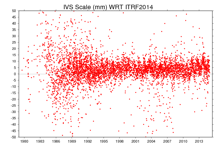
VLBI (Scale)
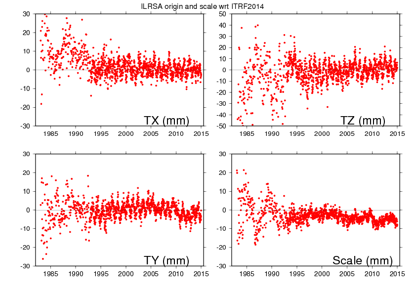
SLR (Scale & Geocenter)
DORIS (Scale & Geocenter)

ITRF2014 files
SINEX and other files
The ITRF2014 files are available via FTP :
 ftp itrf-ftp.ign.fr
cd pub/itrf/itrf2014| Description | Download link |
|---|---|
| IVS Station positions & velocities | |
| IVS Station positions & velocities & EOPs starting from 1979.0 | |
| ILRS Station positions & velocities | |
| ILRS Station positions & velocities & EOPs starting from 1983.0 | |
| IGS Station positions & velocities | |
| IGS Station positions & velocities & EOPs starting from 1994.0 | |
| IDS Station positions & velocities | |
| IDS Station positions & velocities & EOPs starting from 1993.0 | |
| Complete EOP list file: one line per day (MJD) listing all parameters estimated for that day | |
| Complete EOP list file: one parameter per line | |
| 4 files (one per technique) of station discontinuities, in SINEX format | VLBI SLR GNSS DORIS |
| 4 files (one per technique) of post-seismic deformation model parameters, in CATREF internal format | VLBI SLR GNSS DORIS |
| 4 files (one per technique) of post-seismic deformation model parameters, in SINEX format | VLBI SLR GNSS DORIS |
| Equations for post-seismic deformation models and their variance propagation |
Subroutines in Fortran
SSC files
Tables of ITRF2014 coordinates
- VLBI Station Positions/Velocities table
- SLR Station Positions/Velocities table
- GNSS Station Positions/Velocities table
- DORIS Station Positions/Velocities table
Discontinuity files
Some stations have several coordinates supplied in the ITRF2014 solution. Each coordinate (position and velocity) is identified by an integer number called solution number (soln). Coordinates for each soln are valid for a period supplied in the discontinuity files. These periods may be different from the periods stored in the epoch block of the SINEX file which correspond to the observation spans used to determine ITRF2014 coordinates. They do not always reflect the exact epoch of the event that cause the discontinuity in the position time series when it is known that's why these files supply complementary information.
IERS whole network file at the time of ITRF2014
ITRF2014 tie and space geodesy discrepancies
Transformation Parameters from ITRF2014 to ITRF2008
$$\global\def\fig#1{\scriptsize\textcolor{E83E8C}{fig.#1}}$$
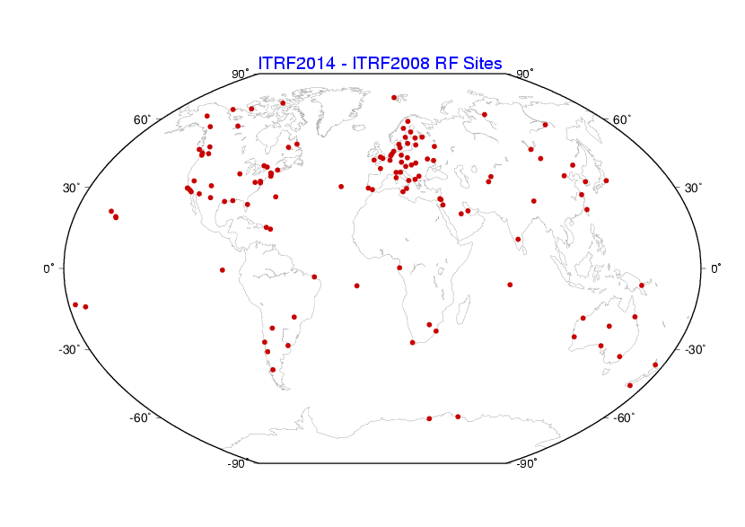
14 transformation parameters from ITRF2014 to ITRF2008 have been estimated using 127 stations listed in the core network list and located at 125 sites shown on the map below ($\fig2$).
| T1 mm |
T2 mm |
T3 mm |
D 10-9 |
R1 mas |
R2 mas |
R3 mas |
|
|---|---|---|---|---|---|---|---|
| 1.6 | 1.9 | 2.4 | -0.02 | 0.000 | 0.000 | 0.000 | |
| $\pm$ | 0.2 | 0.1 | 0.1 | 0.02 | 0.006 | 0.006 | 0.006 |
| Rates | 0.0 | 0.0 | -0.1 | 0.03 | 0.000 | 0.000 | 0.000 |
| $\pm$ | 0.2 | 0.1 | 0.1 | 0.02 | 0.006 | 0.006 | 0.006 |
Transformation parameters from ITRF2014 to past ITRFs are available here
Erratums
The users of the GNSS PSD SINEX file are advised that this SINEX file has been updated for the following stations: ANKR, LEPA, MAC1, P206, and STK2. The PSD parameters for these 5 stations were mistakenly reported in the original SINEX file published in January, 21, 2016. The updated SINEX file was uploaded to the ITRF2014 ftp server on August, 22, 2016. The users should note that the updated values for these 5 stations are the values that were effectively used in the ITRF2014 computation, and are consistent with the values published in the file ITRF2014-psd-gnss.dat.
Acknowledgement
The IERS ITRS Product Center is indebted to the Technique Services (IDS, ILRS, IGS and IVS) and their Analysis and Combination Centers for their contribution by providing reprocessed solutions. The quality of the ITRF2014 is certainly benefiting from technique improved solutions. Many institutions and individuals have also contributed to the ITRF2014 project. We also acknowledge the contribution of DGFI and JPL colleagues to the ITRF2014 analysis. The IERS ITRS Product Center is particularly grateful to all the institutions that provide the necessary investment for the space geodetic observatories which constitute the main ITRF foundation.
Citation: Altamimi, Z., P. Rebischung, L. Metivier, and X. Collilieux (2016), ITRF2014: A new release of the International Terrestrial Reference Frame modeling nonlinear station motions, J. Geophys. Res. Solid Earth, 121, doi:10.1002/2016JB013098.